For a faster response, please include your WhatsApp or Skype in your message so we can contact you as soon as possible.
To help us respond faster, please leave your WhatsApp, email, or project details. We usually reply within 24 hours. For urgent inquiries,contact us on WhatsApp: +8617862411260 or WeChat: +8617862411260. call us directly.
Size a dust extraction pipe from airflow and transport velocity, not fan power. Divide each pickup point’s airflow by the minimum velocity that keeps your dust airborne, convert that area to a diameter, then round down to a standard size. Size the main from the farthest station, enlarging it only where branches join.
Air speed in a duct is airflow divided by the duct’s cross-sectional area. That is the whole relationship. A 315 mm pipe carrying 5,600 m³/h moves air at about 20 m/s. The same pipe carrying 1,500 m³/h moves it at about 5 m/s, and dust drops out onto the floor of the pipe.
Fan power enters the picture only through airflow. A larger fan raises velocity if it actually pushes more air through the same pipe. It cannot rescue a duct that is too wide for the airflow that really flows through it, and that situation is common: the main was sized for every station running, but on most shifts half the blast gates are closed.
Compared with the common shortcut of sizing ducts to match the collector inlet, velocity-based sizing usually produces smaller branches and a main that steps up in diameter along its length. That shape is the visible sign of a network designed for transport rather than convenience.
Settled dust is not only a performance problem. It reduces the effective pipe area, raises resistance, and in combustible dusts creates fuel inside the duct. NFPA 660, Standard for Combustible Dusts and Particulate Solids (2025 Edition) addresses combustible-dust hazards in dust collection systems, and OSHA provides combustible-dust guidance for U.S. general industry.
| Dust type | Branch velocity | Main velocity | Notes |
| Woodworking dust and chips | ~20 m/s (≈4,000 fpm) | ~18 m/s (≈3,500 fpm) | Long chips and shavings need the upper end |
| Light, dry fine dust (many powders) | ~18–20 m/s | ~18 m/s | Check whether the powder is hygroscopic |
| Metalworking and grinding dust | ~23 m/s (≈4,500 fpm) | ~20 m/s (≈4,000 fpm) | Dense particles; expect elbow wear |
| Heavy, moist or sticky dust (e.g. cement) | 25 m/s and above (≈5,000+ fpm) | Same or close to branch | Sticky dust can build up even at high velocity |
Higher is not automatically better. Pressure loss rises roughly with the square of velocity, so running at 28 m/s where 20 m/s would do costs fan energy every hour the system runs, adds noise, and wears elbows faster with abrasive dust. The goal is to stay above the minimum with a sensible margin, not to maximize speed.
The worked example uses a woodworking line with four stations. Machine A is farthest from the collector, D is nearest.
Step 1: Record the airflow each pickup point needs
Take the required airflow from the machine manufacturer’s data or from a hood calculation. Do not use the collector’s rated airflow divided by the number of machines.
| Station | Required airflow |
| A (farthest) | 1,500 m³/h |
| B | 1,200 m³/h |
| C | 900 m³/h |
| D (nearest) | 2,000 m³/h |
Done when: every pickup point has a documented airflow figure and its source.
Step 2: Choose design velocities for branches and main
From the table above, this woodworking example uses 20 m/s in branches and 18 m/s in the main.
Done when: you have one branch velocity and one main velocity, and you have recorded why.
Step 3: Calculate each branch diameter
Use:
For station A: 1,500 ÷ (3,600 × 20) = 0.0208 m², which gives 163 mm.
Done when: each branch has a calculated diameter.
Step 4: Round down to a standard size, then recheck velocity
If 163 mm is not a stock size, choose the next size down, not up. A 160 mm pipe carrying 1,500 m³/h runs at about 20.7 m/s. Rounding up to 180 mm drops it to about 16.4 m/s, below the target.
| Station | Calculated | Selected | Actual velocity |
| A | 163 mm | 160 mm | 20.7 m/s |
| B | 146 mm | 140 mm | 21.7 m/s |
| C | 126 mm | 125 mm | 20.4 m/s |
| D | 188 mm | 180 mm | 21.8 m/s |
Done when: every selected size runs at or above the design velocity.
Step 5: Size the main from the farthest station outward
Start at A and add each branch’s airflow where it joins. Enlarge the main only at a junction, and never step it back down toward the collector.
| Main section | Cumulative airflow | Selected diameter | Actual velocity |
| A to B junction | 1,500 m³/h | 160 mm | 20.7 m/s |
| B to C junction | 2,700 m³/h | 224 mm | 19.0 m/s |
| C to D junction | 3,600 m³/h | 250 mm | 20.4 m/s |
| D to collector | 5,600 m³/h | 315 mm | 20.0 m/s |
If 224 mm is not in your supplier’s range, the next size down (200 mm) runs at about 23.9 m/s. That works, at a higher pressure cost on that section.
Done when: the main increases in diameter at each junction and every section stays above 18 m/s.
Step 6: Lay out the fittings
Most avoidable pressure loss sits in fittings, not straight pipe.
Done when: a layout drawing shows every fitting type, its angle and its location.
Step 7: Calculate system pressure loss and select the fan
Add the losses for the longest or highest-resistance path: straight pipe, each fitting converted to an equivalent length or loss coefficient, the hood entry, the filter at its expected dirty condition, and any spark arrestor or silencer. Select the fan where its curve meets that total pressure at the required airflow.
Done when: the fan’s operating point is plotted at the design airflow and the dirty-filter pressure, not at clean-filter conditions.
Step 8: Measure after commissioning
Measure velocity in each branch with a pitot tube or a suitable anemometer, and record static pressure at the collector inlet. These readings are your baseline. A gradual drop in branch velocity later points to filter loading, a leaking connection or buildup in the pipe.
Done when: a commissioning sheet lists measured velocity per branch and a baseline static pressure.
This is where networks that worked on commissioning day start to fail.
Adding a station. Suppose station E (1,500 m³/h) joins near the collector two years later. The last main section now needs to carry 7,100 m³/h through the same 315 mm pipe, about 25.3 m/s. Pressure loss on that section climbs, and unless the fan has spare capacity, total system airflow falls short of the new demand. The shortfall does not spread evenly. The far branches, with the longest path and the highest resistance, lose the most airflow, so station A drifts below transport velocity first. The symptom reported from the floor is “weak suction at the end of the line,” while the collector itself looks fine.
Closing stations. With a fixed-speed fan and only station A running, the 315 mm section near the collector carries 1,500 m³/h at roughly 5 m/s. Dust from A travels well through its own branch, then settles in the oversized main.
Four ways to plan for this:
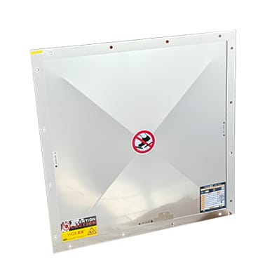
Senserui supplies the components used to build the branch-and-main network described above, including:
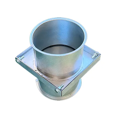
Parameters vary by component and size, and no single specification range applies to the whole category. Diameters, materials and valve actuation options should be confirmed for your project during system design. Pricing for ducting and components is available on request based on system configuration and project requirements, since it depends on network length, diameters, fitting count and safety equipment.
The Senserui Engineering Team supports airflow calculation, duct-network design and safety planning as part of project assessment.
Q: What diameter should a dust extraction pipe be?
A: There is no single correct diameter. It depends on the airflow at that point in the network and the transport velocity your dust needs. Calculate area as airflow divided by velocity, convert it to a diameter, then round down to a standard size.
Q: Will a more powerful fan fix poor suction at the far end of the line?
A: Sometimes, but often not. If the cause is undersized fan capacity after added stations, a larger fan helps. If the cause is an oversized main, leaks or settled dust, more fan power raises energy use without restoring velocity where it is needed.
Q: Is round pipe better than rectangular duct for dust extraction?
A: For conveying dust, round pipe is generally preferred. It holds velocity more evenly across its section, leaves no corners for dust to collect, and is easier to seal.
Q: How often should dust extraction pipes be inspected?
A: Base it on your dust and your measurements. Compare branch velocity and static pressure against the commissioning baseline, and inspect sections where readings change. Combustible-dust facilities should follow the inspection requirements in the standard that applies to them, such as NFPA 660.
Q: Can I add a new machine by cutting a tee into the existing main?
A: Only after recalculating. A new branch changes airflow, pressure and velocity across the network, and the far stations usually feel it first.