Für eine schnellere Antwort geben Sie bitte Ihre WhatsApp- oder Skype-Nummer in Ihre Nachricht ein, damit wir Sie so schnell wie möglich kontaktieren können.
Um uns eine schnellere Antwort zu ermöglichen, hinterlassen Sie bitte Ihre WhatsApp-Nummer, E-Mail oder Projektdetails. Wir antworten normalerweise innerhalb von 24 Stunden. Bei dringenden Anfragen kontaktieren Sie uns über WhatsApp: +8617862411260 oder WeChat: +8617862411260. Rufen Sie uns direkt an.
Ein exhaust gas collection system for VOC sources captures solvent vapor at the booth, flash-off zone or oven, moves it through ducting at a controlled flow, and delivers it to an abatement unit such as an activated-carbon adsorber. Sizing depends on captured airflow and solvent load, not on booth size alone.
What sits between the spray booth and the stack
An exhaust gas collection system is a chain, and each link hands its numbers to the next one:
A mistake at the first link, such as pulling more air than the process needs, turns up later as a larger adsorber, a bigger fan and a shorter carbon life. This guide follows the chain in order and stops where sizing decisions get made.
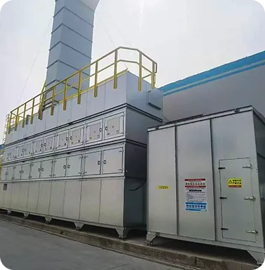
| Emission point | Character of the exhaust | Design consequence |
| Spray booth application zone | High air volume, low solvent concentration, carries overspray mist | Filter mist upstream of the carbon; airflow is set by booth openings, not by solvent load |
| Flash-off / paint leveling room | Solvent keeps evaporating after the gun stops; moderate air movement | Capture has to run through the whole leveling time, not only during spraying |
| Drying and curing oven | Warm, smaller volume, higher solvent concentration | Cool or condition before adsorption; hourly solvent mass can exceed the booth’s despite lower flow |
| Solvent cleaning station | Intermittent, localized, often a single solvent | Small local hood; decide whether it joins the main duct or gets its own line |
Senserui’s HAC lists all four of these process types among its typical applications, alongside chemical and pharmaceutical processes.
Capture flow follows from the geometry of the opening and the inward air movement the process needs to hold vapor in. It does not follow from the adsorber. Extract too little and solvent escapes into the workshop. Extract too much and the same solvent mass is spread through more air, which means a bigger adsorber, more fan energy and a weaker inlet concentration for the carbon to work with.
To set the design flow:
The solvent mass entering the adsorber each hour is:
Solvent mass rate (kg/h) = airflow (m³/h) × concentration (mg/m³) ÷ 1,000,000
Illustrative arithmetic with hypothetical values, not a Senserui specification: 20,000 m³/h at 50 mg/m³ delivers 1 kg of VOC per hour, or 8 kg over an eight-hour shift.
Hours until the carbon is saturated then follow from:
Hours = carbon mass (kg) × working capacity (kg VOC per kg carbon) ÷ solvent mass rate (kg/h)
Working capacity is not one number for “activated carbon”. It comes from the carbon supplier’s data for your specific solvent at your temperature and humidity, and a multi-solvent mix has to be assessed species by species.
Two consequences follow. First, doubling the airflow while the solvent mass stays the same does not double carbon consumption. It enlarges the adsorber and the fan, and it lowers inlet concentration, which typically lowers the working capacity the carbon can reach. Second, saturation is the upper bound on the interval, not the target. Solvent starts to appear at the outlet when the leading edge of the adsorption zone reaches the end of the bed, before the whole bed is full. The replacement interval is therefore set by breakthrough.
Overspray mist that reaches the carbon coats the surface and blocks pores. The result is higher resistance to flow and less capacity, so a filter stage belongs upstream of the adsorber, with its own pressure reading. Heat works against adsorption as well: the warmer the gas, the less solvent carbon holds, so oven exhaust needs conditioning before it enters the bed. Moisture competes with solvent for adsorption sites in some conditions, which matters most in humid climates and with water-borne coatings mixed into the exhaust.
Senserui lists differential-pressure monitoring on HAC. Where the pre-filter stage sits inside a HAC-M layout is not stated on the product page, so confirm that in the quotation.
Senserui’s HAC / HAC-M Modular Exhaust Gas Treatment System is an activated-carbon adsorption unit. This table separates what the product page states from what you should still ask for.
| Parameter | Published information | Ask for |
| Adsorbent | High-iodine-value honeycomb activated carbon | The iodine value figure and solvent-specific capacity data at your conditions |
| Architecture | Modular, multi-fan | Number of fans and modules for your airflow; behavior at reduced load |
| Carbon change-out | Replaceable carbon cassette design | Cassette count, carbon mass per cassette, change-out time, spent-carbon handling |
| Monitoring | Differential-pressure monitoring; breakthrough monitoring; optional IoT monitoring | Sensor type, alarm setpoints, data export format |
| Applications | Spray booths, paint leveling rooms, drying and curing, solvent cleaning, chemical and pharmaceutical processes | Fit for your solvent mix and inlet temperature |
| Airflow and power | No fixed range published; configured to airflow and VOC concentration | Rated airflow and kW for your configuration |
| Certification | No product-specific certificate number published | Which certificates apply to the delivered unit |
| Price | Available on request based on system configuration and project requirements | Quotation |
Iodine value is an index of micropore development in the carbon. It is a quality indicator, not a guarantee of capacity for any particular solvent, so a figure on its own does not tell you how long a fill will last. Honeycomb carbon is generally chosen to keep resistance to flow low. HAC pressure drop is not published, so read fan power at your flow from the quotation.
Compared with common single-fan adsorber packages, a multi-fan modular layout lets several smaller fans share the airflow. Senserui describes this as demand-based operation for energy management across its systems. HAC-specific energy figures are not published.
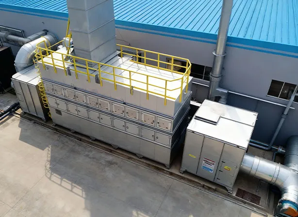
Differential pressure measures resistance to flow. It rises when mist, dust or condensate clogs the media, and it says nothing about whether the carbon still adsorbs. A breakthrough monitor detects solvent leaving the carbon. The two signals answer different questions, and reading them together separates a maintenance problem from a capacity problem.
| Differential pressure | Breakthrough signal | Likely meaning |
| Normal | None | Carbon and pre-filter are both in working condition |
| High | None | Pre-filter or carbon face is fouling; capacity may be intact |
| Normal | Alarm | Carbon is approaching or past saturation; flow path is clear |
| High | Alarm | Fouling and saturation together; check what changed upstream |
A saturated bed can show a low pressure drop, which is why a bed can look healthy on pressure alone while solvent passes through it.
To set the replacement interval from measurement rather than the calendar:
| Layout | Exhaust volume | Concentration at adsorber | Fugitive risk | Typical fit |
| Full enclosure or booth with controlled openings | High | Low | Low if held under negative pressure | Spray booths |
| Local hood or slot at the source | Low to moderate | Higher | Depends on hood position relative to the part | Cleaning stations, small parts |
| Enclosed oven exhaust port | Low | Highest | Low | Curing ovens |
| General room ventilation | Very high | Very low | High | Rarely practical for carbon adsorption |
Adsorbing room air is usually impractical because the volume is large and the concentration is thin. Hooding the point of release costs more design effort but shrinks everything downstream.
Carbon adsorption suits streams like booth exhaust: large volume, low to moderate solvent concentration, no fuel or flame required. The cassette design confines maintenance to replacing carbon modules rather than rebuilding a bed.
The limits decide projects more often than the strengths do. Carbon is a consumable, so recurring cost scales with solvent mass rather than with airflow, and a high-concentration stream such as oven exhaust can shorten change-out intervals sharply. Adsorption transfers solvent from air to carbon; it does not destroy it, so spent carbon becomes a waste stream to handle under local rules. Hot or humid streams need conditioning before they reach the bed. For a line dominated by curing-oven load, the design stage should test whether all of that flow belongs on carbon.
Price: available on request based on system configuration and project requirements.
Configuration depends on airflow and VOC concentration, so the quotation needs these inputs:
The collector is the capture device at the source: a booth, hood or oven exhaust port. The treatment unit, such as an activated-carbon adsorber, sits downstream and removes the VOC from the captured stream. Errors in collector design change what the treatment unit receives.
Per emission point, from the opening geometry and the inward air movement your process needs. Flows of sources that run at the same time are added, and the total is checked against the adsorber’s rated airflow.
There is no universal interval. It depends on solvent mass rate, carbon mass and working capacity, and it is best set from the breakthrough trend. Senserui has not published a replacement interval for HAC.
No. The product page says configurations are adapted to airflow and VOC concentration and gives no fixed numerical range.
Senserui states company-level ISO 9001:2015 quality management, CE compliance and explosion-protection design based on ATEX principles. No product-specific certificate number is published for HAC, so request the certificates that apply to your delivered unit. The European Commission’s CE guidance places responsibility for identifying applicable requirements on the manufacturer.
It depends on whether their schedules, temperatures and concentrations are compatible. Combining them without a configuration review risks feeding hot, concentrated oven exhaust into a bed sized for dilute booth air.